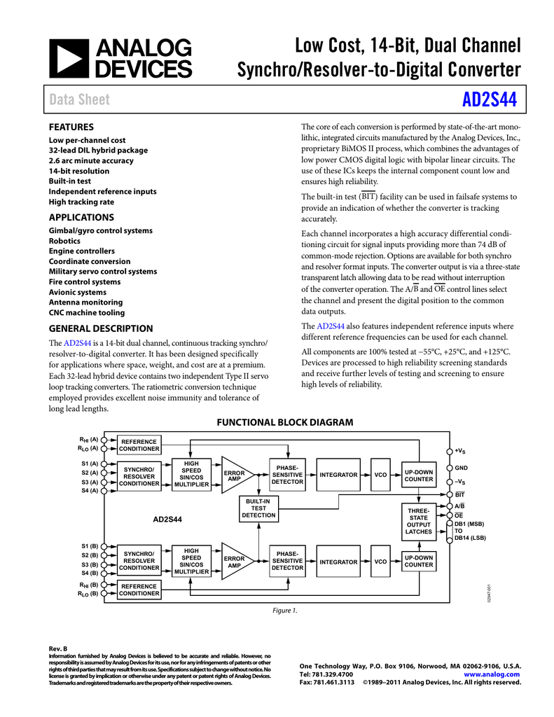
This can be accomplished by using a synchro-to-digital converter. Synchro-to-Digital Conversion Synchros generate analog output signals, and those outputs must typically be converted to digital form. For that reason, small aircraft synchros are excited with 400 Hz signal. A small magnetic core saturates when driven with 60 Hz. Reducing the size and weight of a synchro reduces the size of its magnetic core. This reference signal is typically one of two possible voltages: ġ15 VRMS 60 Hz or 400 Hz 26 VRMS 400 HzĤ00 Hz signal is used in aircraft applications, where size and weight are important factors. A synchro is excited by an AC reference voltage applied to its rotor winding. The relative amplitude of the resulting AC output signals from the secondary (stator) windings indicates the rotary position of the transmitter’s shaft.

As the shaft of a synchro transmitter is turned, the angular position of its rotor winding changes with respect to its secondary (stator) windings. A synchro can be turned continuously and, since its secondary winding outputs are analog signals, provide "infinite" resolution output.

Synchros are often used to track the rotary output angle of a closed-loop system, which uses feedback to achieve accuracy and repeatability. 3 – Resolver Rotor/Stator Configuration similarity, the term "synchro" will be used to refer to both Synchros and resolvers for the remainder of this article, unless otherwise noted. The secondary windings (which relationships are fixed) are called stators. For this reason, the primary winding is Output voltage R3 called the rotor. The primary R4 winding in a synchro or a resolver can be R2 physically rotated with respect to the secondary windings. While a synchro and a resolver are electrically very similar to a transformer, they are S3 mechanically more like a motor. In contrast, as shown in figure 3, a resolver has: Ģ primary windings 2 secondary windings, which are oriented at 90º to each other 2 – Synchro Rotor/Stator Configuration S1 As shown in figure 2, a synchro has: Ģ primary windings 3 secondary windings, with each secondary winding mechanically oriented 120º apartįig. Just like a traditional transformer, they have a primary winding and multiple secondary windings, and just like a transformer, their primary is driven by an AC signal. Theory of Operation Synchros and resolvers are World War II era technology that is still widely used in modern day electronic motion control applications. TO RECEIVER LOOP ANTENNA INPUT INDICATOR MOTOR FROM RECEIVERįig. 110 Wilbur Place, Bohemia, NY 11716įlight surface positioning cockpit simulators jet engine control antenna pedestal control cockpit indicators landing gear positioning and control flap actuators RESOLVER FIXED COIL ROTATING COIL The analog waveforms generated by these transducers, and their characteristics, are detailed in the ARINC407 specification (ARINC Synchro System Manual), but how do synchros and resolvers work specifically? North Atlantic Industries, Inc. As the aircraft turns, the amount of coupling in the transducer changes proportionally as illustrated in figure 1.


Synchros & Resolvers Synchros have been used in a wide variety of military and commercial systems for many years. This article will address the systems that utilize these transducers, de-mystify the workings of these AC analog transducers and associated conversion electronics, describe the testing and simulation of these signal types and discuss some common troubleshooting failure mechanisms. Motion Electronics in Avionics Several transducer types, including synchros, resolvers, linear/rotary variable differential transformers (LVDT/RVDT) are key building blocks in flight control and navigation dynamics.


 0 kommentar(er)
